On this page
Nodes are displayed as gray boxes in the Work Area. Each node has different input and output channels (sockets) depending on the type.
Root Node
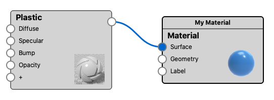
All materials have one Root node which is marked with a thicker border (fig. 1). All nodes must be connected to the root node, either directly or through other nodes, to have an effect on the material.

Connected Nodes
Connections are made by clicking on an output channel and dragging and releasing directly onto a specific input channel, the + socket or onto the node itself. When it is released onto the + socket or the node, a context menu will show all of the available channel options.
Once a connection is made, a blue line will appear connecting the 2 nodes. Right click the line to remove or disable the connection. A disabled connection will be displayed as a grey dashed line. If you select a connection, it will turn light blue.
Selected Node
The node with a slightly lighter grey background is the currently selected one (fig. 2).
The selected node is the one that will be impacted by the node options in the material graph ribbon (as well as hotkeys).

The node that has an orange outline is the one shown in the Material Properties panel inside the Material Graph. Double click a node to see the properties for that node.
Node preview options:
The Material Graph’s node preview options enable you to adjust your texture node, while you can see it on the model in the Real time view.
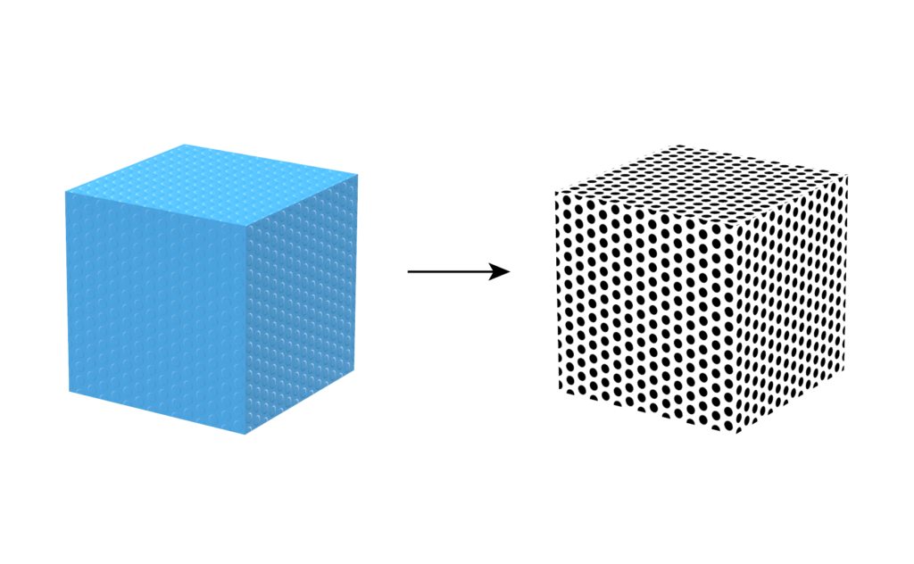
![]() Preview Color – This preview shows the color of texture before it is used to alter the material (fig. 3). The Hotkey C will toggle the color preview.
Preview Color – This preview shows the color of texture before it is used to alter the material (fig. 3). The Hotkey C will toggle the color preview.
![]() Preview Alpha – This preview shows the alpha channel on the texture, before it is used to alter the material. If you want to use the Alpha channel to mask out the Opacity, you need to set the Opacity Map Mode to Alpha, on the material receiving the texture, otherwise the opacity will be created using the color of the texture. The Hotkey A will toggle the alpha preview. Note that the only procedural texture that includes an alpha channel is the Mesh texture all the others will just appear solid.
Preview Alpha – This preview shows the alpha channel on the texture, before it is used to alter the material. If you want to use the Alpha channel to mask out the Opacity, you need to set the Opacity Map Mode to Alpha, on the material receiving the texture, otherwise the opacity will be created using the color of the texture. The Hotkey A will toggle the alpha preview. Note that the only procedural texture that includes an alpha channel is the Mesh texture all the others will just appear solid.
![]() Preview Bump – This preview shows the texture will be translated into a normal map, which is the basis for the bump effect. The Hotkey B will toggle the bump preview.
Preview Bump – This preview shows the texture will be translated into a normal map, which is the basis for the bump effect. The Hotkey B will toggle the bump preview.
To exit any preview mode you can use the hotkey X.


Tip
For better control and easier editing, select your desired node and press C to view the texture map on your model. In the example above, the Bump node is selected and isolated on the model in the real-time view.
Multi-Materials
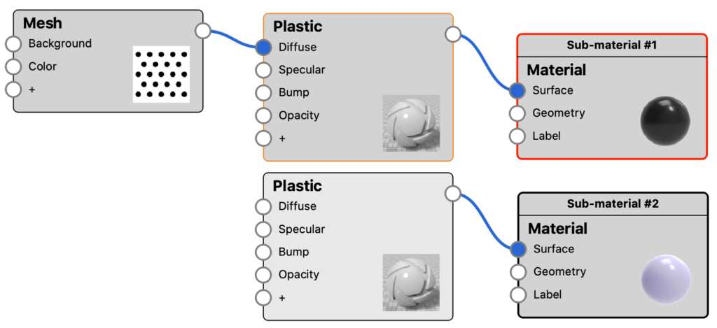
If you have a Multi-Material shown in the Material Graph, all variations will be visible. The active material will have a red outline (fig. 4).
Material Properties
The node that has an orange outline (fig. 4) is the one shown in the Material Properties panel inside the Material Graph. Double click a node to see the properties for that node.
