On this page
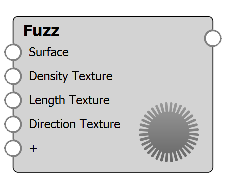
The Fuzz node enables you to add randomized, hair-like growth from the surface of any material. To make the fuzz appear on your geometry, connect the Fuzz node to the Geometry socket of the root Material node.
Fuzz Settings
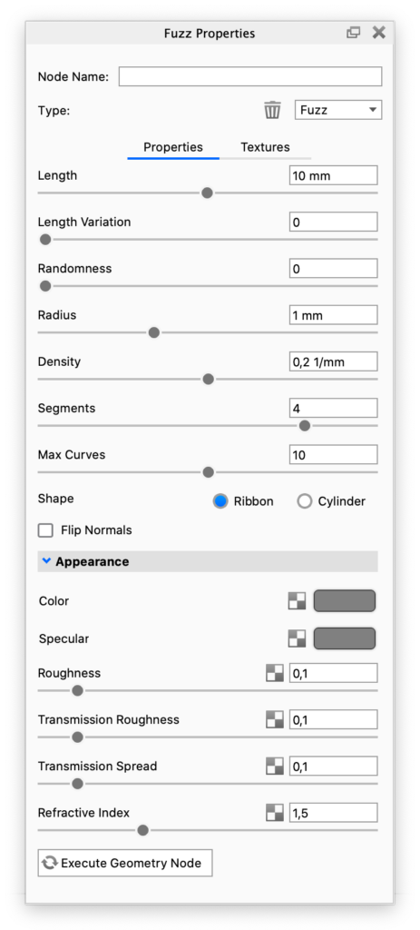
Length: This determines the base length of the fuzz fibers.
Length Variation: Adds variation to the fuzz fiber length. The fibers will be varied up to the selected length + length * variation value.
Randomness: By default the fuzz fibers are straight. Increasing Randomness will add variation to the flow of each fiber.
Radius: Set the width of each fuzz fiber.
Density: Adjust how many fibers are added within 1 unit.
Segments: Determines the number of segments each fuzz fiber consists of. Increasing the number of segments will produce a smoother fiber. If you have added length variation to the fuzz, the varying fibers will have proportionally more/less segments.
Max Curves: This value limits the amount of curves the fuzz material can generate for each part. Adding large amounts of curves can make the scene very heavy. The amount of curves are impacted by both density, length variation and segment values. If the curve limit is reached, the density will be impacted. The Max curve value is measured in millions and is an approximation. If you don’t want to limit the amount of curves just leave the value at 0.
Shape: Select if you want the fuzz fibers to have a Ribbon or Cylinder shape.
Flip Normals: The fuzz direction follows the normals. Flip Normals will make the Fuzz go in the opposite direction.
Appearance
The following parameters will only affect the fuzz fibers, not the base geometry.
Color: Sets the base color of the Fuzz fibers.
Specular: This is the color and intensity of the reflection of light sources within the scene. Black will completely turn off reflections, while white will provide a very shiny plastic look. To achieve the most realistic look, use some level of gray or white. Adding color can give the material a metallic effect.
Roughness: This will add microscopic levels of imperfections to the surface fibers when the values are increased. When set to 0, the material will appear perfectly smooth and polished. When the value is increased, it will appear more rough as light is diffused across the surface.
Transmission Roughness: Increasing this value will spread out highlights on the surface, similar to what you see on non-transparent materials. However, it also spreads out the light that is transmitted through the material.
Transmission Spread: This controls the spreading of light as it passes through the fuzz fibers.
Refractive Index: This controls how much light will bend or “refract” as it passes through the fuzz fibers.
Connected nodes
Surface
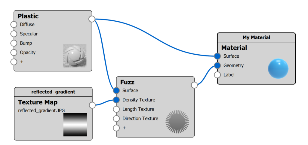
Adding a material to the Surface socket of the Fuzz node will enable you to customize the material of the fuzz fibers. This means that when a Surface node is attached, the Appearance parameters in the Fuzz node will be disabled.
Density Texture
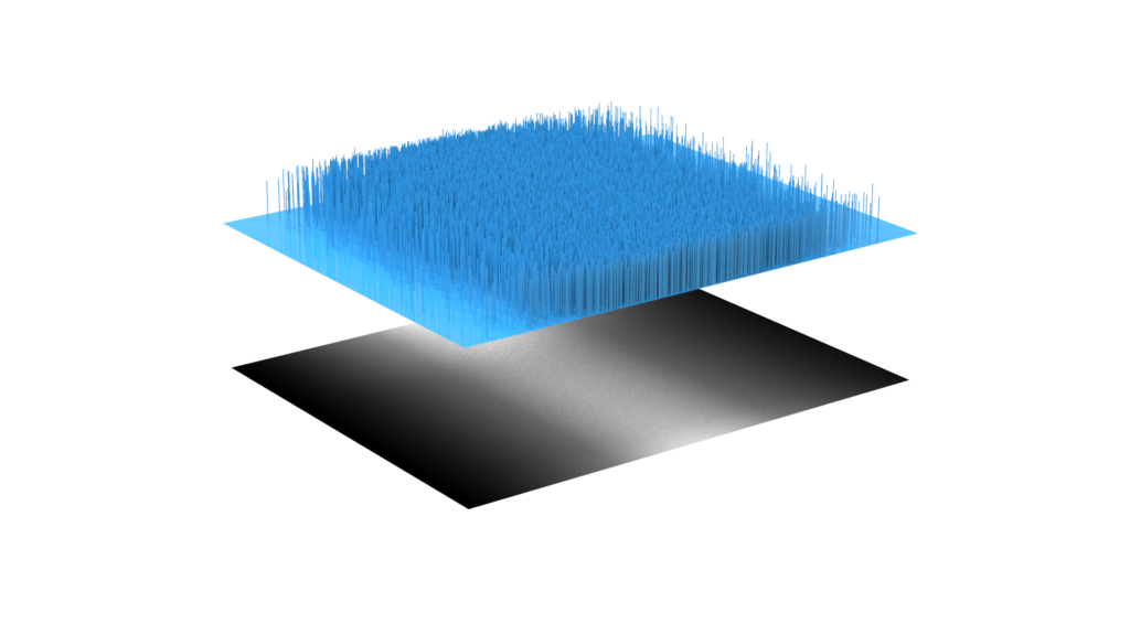
The Density Texture enables you to add variation to the density of the fuzz fibers. In white areas, the density will match the value you entered in the Density parameter above, while darker areas will have less fuzz fibers.
In this example the bottom plane shows the texture, used to manipulate the fuzz density in the the top plane.
Length Texture
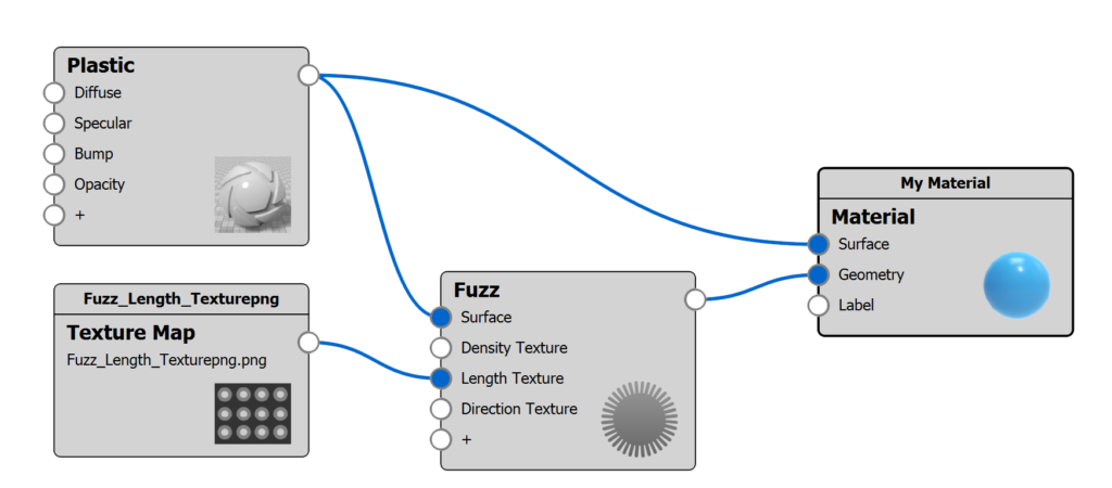
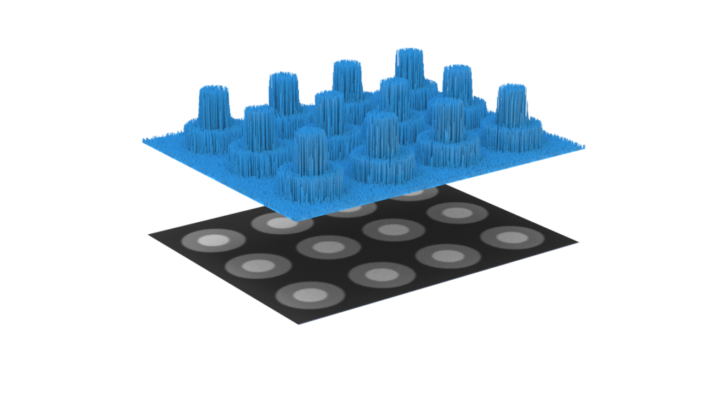
Where the Length Variation adds randomness to the length of the fuzz fibers, the Length Texture enables you to manipulate the length based on a texture. This will act as a mask to the length, while still taking the Length Variation into account. 100% white will result in the length defined in the parameters above, while darker colors will produce shorter fuzz fibers.
In this example, the bottom plane shows the texture used to manipulate the fuzz length in the the top plane.
Direction Texture
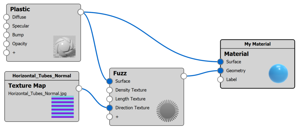
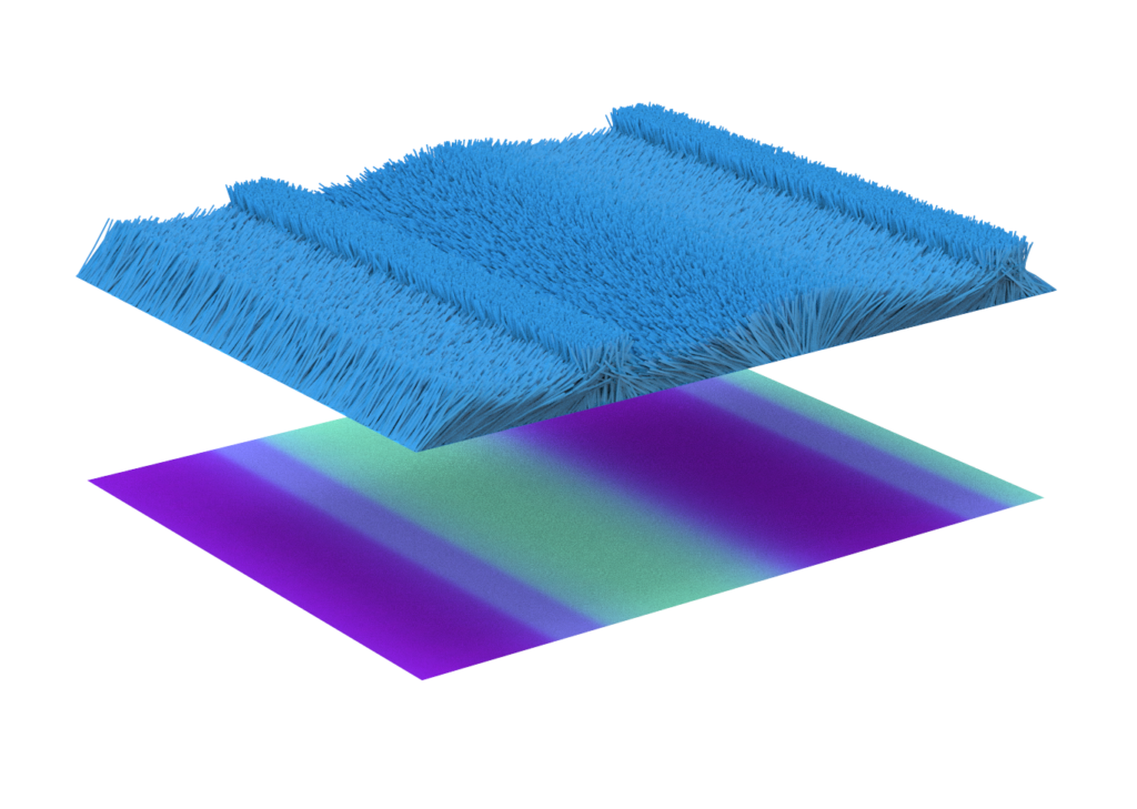
By default the fuzz fibers will follow the geometry’s normals. Adding a Direction Texture will enable you to manipulate the direction at which the fibers come out of the surface. You can use either a normal map (image texture) or a procedural texture (not color gradients). The Bump Height of the Direction Texture controls how much the direction is altered. At a bump height of 0, fibers will follow the normals. Increasing the value will increase the angle. Negative values will angle the fibers in the opposite direction.
In this example, a normal map is used to manipulate the direction. The bottom plane shows the texture, used to manipulate the fuzz direction in the top plane. In the first image, the bump height on the texture map is 1, while it is -1 in the second image.
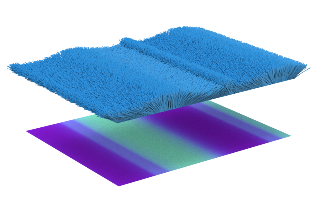
In the following example, a procedural texture, cellular, is used to randomize the fuzz direction. The bottom plane shows the texture, used to manipulate the fuzz direction in the top plane.
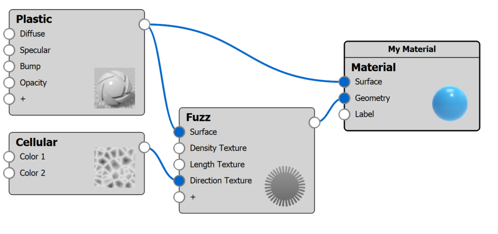
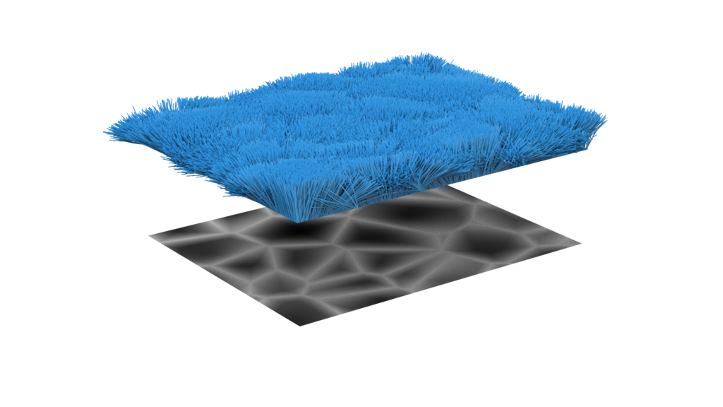
The direction texture determines the angle at the base of each fuzz fiber. If you increase the Random value, this will make the direction less pronounced.